Archive
Archive for the ‘1-way’ Category
‘Audrey’ Horn-loaded Single-driver Loudspeaker System – by Nathan P. Miller
April 28, 2010
8 comments
General Overview
I wanted to build a pair of loudspeakers that was out of the ordinary and involved a bit more thought than just throwing drivers in a box and tuning it. I didn’t, and still don’t, have a specific use for these speakers – I mostly just wanted to take the class and learn about something I enjoy. I had been looking up horn-loaded systems for almost a year and even developed a front-horn driven system for our Audio Engineering Society’s Winter Carnival statue (see here) so obviously I had a large interest in making something horn-loaded for my Transducer Theory project.
Another interesting loudspeaker concept that I’ve spent a while looking at – and one that is deeply connected with horn-loaded systems – is the small niche of “single-driver” systems. These would feature one single driver that would be responsible for producing the entire range of frequencies. That would mean that it would have to be light enough for extremely high frequencies yet stiff and strong and powerful enough to provide enough compression for a reasonable bass response. I suppose for some who have not researched much into this sort of thing it would seem nye impossible to accomplish, but there are many speaker manufacturers who specialize in this sort of thing (i.e. Lowther, Fostex, some of Tang Band’s, Audio Nirvana, etc.).
I would also like to point out that both horn driven systems and even single-driver systems were much more popular before the advent of extremely high gain amplifiers (read: the tube amp era) and are certainly not a new technology of any sort. For further evidence of this fact, the Tractrix horn curve that I used for my system here was patented in 1927 by Paul Voigt.
Finally, another great part about having a single driver is that you don’t have to use crossovers that can (and more often then not) mess up phase relationships between drivers, degrades off axis response, and need to be designed well enough to maintain a relatively flat response. Not that I’m trying to hate on crossovers – I’ve had to use them A LOT – but the prospect of all frequencies coming from a single source with no phase discrepancies just seams appealing.
My Design Goals
To make a full-range single-driver rear-horn loaded loudspeaker system. Given the proper driver, this would allow a range of 50-20kHz ± 5dB from one source. Sound would be naturally phase-aligned and would not be affected by crossover issues. And the name ‘Audrey’ has no significance other than so you can later reference this specific design as opposed to the general category.
Horn Design
I definitely want to start this off with letting you know that I am NOT an expert on horn design or even transmission line systems. I have done a lot of research into horn design, transmission line, and even quarter-wavelength theory designs and without trying to simplify it too much, they all try to accomplish the same thing: controlling the pressure waves induced by low frequency speaker excursion. In hindsight, I feel lucky that my design worked as well as it did because of the fact I did most of the math and designing by hand.
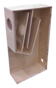
I modeled my horn off of the Tractrix formula but also integrated a little transmission line folding and quarter wave theory. I refuse to say that I knew entirely what I was doing, but my thought process seemed reasonable. To build a horn you generally have to have a rather large throat expanse which is preceded by a correctly tuned compression area and is followed by a specific horn-mouth cutoff which generally dictates what frequency your horn stops functioning at. Quarter-wavelength theory relies on standing waves that are a quarter the size of a normal single full-wavelength and therefore have four times the length and thus one fourth frequency (read: sort of gives you free low frequency response, link). And finally, transmission line systems are nearly always about how to fold it into a tight space. I sort of took all three of these and slapped them together like I knew what I was doing; again, luckily it worked out as well as it did.
I decided on an internal width of 250mm (mostly because i like SI units as an engineer) because it would fit my driver well and from here started doing the math for my horn. I realize that horn design is all about flare-rate and is quite dependent on the thickness, but I just did a simple one-dimensional horn and simple extruded it 250mm to match. I pretty much folded it the best I could so that it fit well; I did this while I was 3d-modeling it (UG NX5), so it was pretty easy to set constraints and let the program figure it out. Not much beyond this was done in terms of designing the horn. I did, however, spend a very large amount of time in Excel and on paper figuring out the right dimensions at all joints so that the horn-flare was followed as best as possible; it was hard to have an ever increasing flare without curving each board.
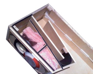
Fiberglass helps reduce rear reflections through the woofer cone and gasket tape increases how well the box is sealed.
Cabinet Construction
The construction was a lot more work than I thought it would be. It was a very involved process with many, many angles to consider and my choice of using 45° angle butt-joints was not a terrifically smart move because of the complexity and precision necessary (although it didn’t look too terrible from the front, which was my objective). I used three sheets of 4’x8′ 11-ply birch plywood and the cut-out diagram can be found on the last page of the engineering drafting drawings PDF (here). The most intriguing part of the build was that I put magnets behind the front baffle (completely hidden) and made a speaker grill to snap into place over so as to protect the very delicate driver; it’s very cool to have the grill just *snap* into place when you can’t even see the magnets it connects to.
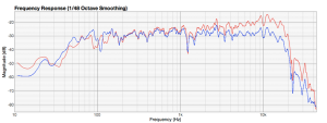
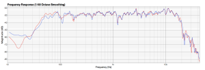
Another important construction step was tuning my box/horn to get the most out of it. The main things that I had to worry about for my design was sealing the box (but temporarily so that i could get in/out) and then simple reflections coming from the back inside wall. These were both alleviated through normal loudspeaker design methods which included gasket tape around the compression chamber to get better lower frequency response and fiberglass on and around the compression chamber to greatly reduce reflections. The increase in bass response can actually be seen in the Before/After Tuning image below.
Driver Choices
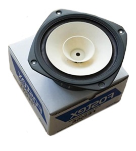
I chose to use a Fostex FE206E 8″ driver mostly because it was relatively cheap and fit perfectly with what I planned to do; it was made for rear-horn applications and – unlike the higher-end FE208EΣ – didn’t require the use of a super-tweeter. There were many accounts on the internet that had great success with this driver and with a few simple modifications could be made much better (various methods of phase plugs, frame dampening, and cone modification have been tried – a google search for “FE206e modifications” will show you a few) and so these examples of great loudspeaker systems only convinced me moreover to use the Fostex driver. Interestingly enough, however, when I went to order the FE206E from Madisound they said that it was discontinued and after a few stressful emails (I had designed my cabinet for these things after all), it turned out that they were being discontinued simply because Fostex had come out with a newer revamped version: the FE206En (yeah, the ‘n’ stands for ‘new’). Specs for this new driver can be found in the key features section below (here). Some of the new changes are a much lower moving mass (15g to 12g) and a slight change in magnet strength. The new changes didn’t affect my design and were only going to improve on the sound quality.
Baffle-Step Compensation
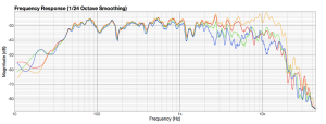
Regardless of my attempts at avoiding passive crossovers, it was probably inevitable that I ended up needing to develop a baffle step to compensate for my very fatiguing high frequencies (which is kind of ironic because they’re coming from a full-range woofer). I got general schematics off of the internet somewhere of a baffle step (pretty basic) and the modeled it in LinearX’s LEAP Crossover Shop to fine-tune it to my liking. I ended up needing to de-wind an inductor to get a better value out of it, but the end result was a very nice and flat response. Sadly, because the high frequencies dropped off so steadily off-axis I decided it would be better to have them a little higher on-axis to compensate. I’m still happy with this decision; they remain quite bright and don’t have the ear-piercing fatiguing sound as before.
Key Features
• New (March 2010) Fostex FE206En 8” Full-range drivers
◦ Designed for rear-horn applications
◦ Cone made of banana fiber and weighs just 12.2 grams
◦ Low mass allows for quick and accurate response
◦ 96dB/1m – even low wattage amps will work great
•3-meter folded-horn/transmission-line
◦ Designed using Tractrix formula
◦ Contains key features of both horn and t-line
◦ Allows for fuller bass response (down to 50Hz)
◦ Lowers distortion at mid to low frequencies
•Baffle-step Compensation
◦ Used to lower high frequency response
◦ Decreases listening fatigue significantly
Specifications:
•Size: 4 feet tall, 11¼ inches wide, 25½ inches deep
•Weight: around 50lbs per cabinet
•Response: 45Hz to 18.5kHz ± 5dB
◦ f3: 45Hz
◦ f10: 41Hz
•Power: 30W nominal power handling
•Loudness: capable of 85dB w/ 20dB headroom at two meters
Documents:
•Speaker Leaflet/Glossy (.pdf, 3.27MB)
•Design Proposal (.pdf, 763KB)
•Engineering Drawings/Drafting (.pdf, 383KB)
•Component Budget Breakdown (.pdf, 81KB)
•Photo Journal (.pdf, 1.41MB)
Measurements:
•Before (red) and After (blue) tuning:
•Off-axis response (Yellow=0°, Red=15°, Green=30°, Blue=45°):
•Left and Right Frequency Response:
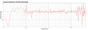
•Left vs. Right Frequency Response Difference:
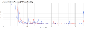
•Harmonic Distortion (Left and Right):
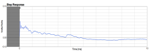
•10ms Step Response:
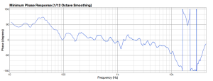
•Minimum Phase Response:

The Audrey system by Nathan P. Miller is licensed under a Creative Commons Attribution-Noncommercial-Share Alike 3.0 United States License.
Categories: 1-way, 40-60lbs, 5-8, Horn Loaded, Passive, Tower/Floor Standing
Fostex, Full-range, Horn, Rear-Horn, Single-Driver, Tractrix

